About Me

Sunday, October 10

RGB LED Mood Light

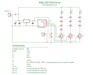
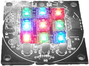
  This project is an update to the original RGB LED PWM Driver.  The new version allows the use of either 5mm LEDs or the square bodied Superflux / Piranah style LEDs.  The circuit now uses bipolar transistors rather than MOSFETs which make it more suitable for novice constructors and for the first time this project is available as a kit with all parts required to assemble the PCB including the superflux LEDs.(power supply not included)
Full schematic and construction details are shown on this page, as well as the firmware download for those who want to create their own effects or build their own version from the schematic.  If you're not into programming the kit includes a PIC microcontroller pre-programmed with the firmware and a number of mood lighting effects.
Circuit Description
The circuit itself is fairly straightforward.  Diode D1 provides reverse polarity protection for the board in case the power supply is connected backwards.  C1/C2 and IC2 take the incoming 12 volt supply and provide a regulated 5 volt supply required by the PIC microcontroller.
The red, green and blue LEDs are arranged in three parallel strings of three LEDs.  Resistors R1, 2 and 3 limit the current through the LEDs to a safe value when using a 12 volt power supply. The low side of each LED string connects to a BC547 NPN transistor which is used to switch the LEDs on and off.  These transistors are in turn controlled by the PIC microcontroller which drives each of the red, green and blue channel transistors with a PWM signal to control the average brightness of the LEDs.  Switch S1 is used to select different effect sequences.   The firmware program running on the PIC microcontroller is the smart part of the circuit and determines what colours are generated and how they fade from one colour to the next.
The three colours of LEDs are positioned on the PCB in an irregular arrangement to improve the colour mixing effect when placed behind / inside a diffuser such as a frosted glass globe.
The controller uses (RGB) Red, Green and Blue high brightness LEDs that are pulse width modulated (PWM) to vary the intensity of each colour LED.  This allows effectively any colour to be generated with rapid changing strobe effects, fast and slow colour fades as well as static colours.   The data used to set and change the colours is held in an easy to edit file so if you don't like the sequences provided with it, you can modify the sequence data include file yourself and reprogram with your own sequences.(you will need a PIC programmer and some practical knowledge of microcontrollers and programming if you want to do this.)


download source code

download hex file

Wednesday, September 29

PIC DIE

Electronic Die

Built using a PIC16F84, about 4 hours worth of code and a few bits on a breadboard. This was the first time I've worked with PIC's so it was a learning exercise. I started with the 'Hello World' microcontroller equivalent i.e.  Blinking LED, then tried the 'Knight Rider' sequencing LEDs, and then hacked this together. The code is written and assembled using the Microchip MPLAP IDE V5.70.  I only did this as an exercise to familiarise myself with PIC assembler, but having got it working I decided I wanted it smaller and as I had just acquired some 12F675s I took the original 16F84 code and developed it further to work with the 12F675.


Source code (the 12F675 die source below is better documented and developed)


Hex file ready to program (right-click Save As)


Circuit schematic

Monday, September 27

LONG PERIOD ASTABLE

Description
This software functions as a long period astable mutivibrator.  The mark and space period can be set from 1 second up to a maximum 65535 seconds (18h12m15s). Using the internal 4Mhz RC oscillator delays with an accuracy of 99% or better can be achieved 
The code also implements an edge triggered reset and an active low hold function.  The reset edge can be configured for rising or falling edge.  The hold function is active low and stretches the timed period for as long as the hold input is held low.
In addition to this up to 450 mark/space time pairs can be used which are executed sequentially allowing complex pulse trains to be generated.
By connecting the hold input to the Q output, the code can also be made to function as an edge-triggered monostable timer, using the reset input as the trigger.
The code will run on a PIC 12F629 or 12F675.
Pin functions

At power on and after an edge triggered reset the outputs enter a mark state with the Q output going high and the notQ output going low.  The first time entry is then read and the code waits for the number of seconds specified.  When this period has elapsed a Space state is entered with the Q output going low, notQ output high and the next time entry is read. 
When the Hold input is taken low the output remains unchanged and the timer is stopped, effectively stretching the current time period. When the Hold input returns high, the timer continues.
If the Reset input is triggered while Hold is low, the outputs are reset to Q == high, notQ == low and the timer is loaded with the first entry from the LongDelayTimes.inc file. It them remains in the Hold state until the Hold input returns high.


Circuit diagram


Download circuit diagram in pdf

Download source files

Download hex file

Sunday, September 26

PIC FREQUENCY COUNTER USING 16F877A


This PIC frequency counter circuit uses a multiplexed seven segment display and uses timer 1 to count edges of the input signal.
It uses the simpler method of direct frequency measurement which is easy to do but means that the number of digits displayed depends on the input frequency. 
Note: If you want to display all digits all the time there is a technique calledreciprocal counting - but this requires floating point (maybe fixed point) routines and would be difficult to implement with this hardware since it needs constant time routines to count accurately.


Specification of the frequency counter circuit

Min frequency1Hz
Max frequency~50MHz (limited by input pin characteristics).
Input signal levelTTL


The major difference in this project is that the display must be continuously refreshed so that your eye is fooled into thinking that display as is not flickering (persistence of vision).
For this frequency counter circuit project the display is refreshed every millisecond which is excessive - but does work. This refresh rate was chosen due to the timing period of the gate loop (999us) and allows easier constant time operation. Your eye only needs a refresh rate of about 50Hz or 20ms.


source code for pic 16f877a


//////////////////////////////////////////////////////////////////////
//
// File: Frequency-counter-4MHz-7seg-TMR1.c
//
// Author: rohith t
//
// Description:
//
//   Measure frequency using TMR1 up to about 50MHz (depends on PIC chip input).
//
//   Displays result on 8 x 7segment display.
//
// Compiler : mikroC, mikroElektronika C compiler
//            for Microchip PIC microcontrollers
//            Version: 5.0.0.3
//
// Note Testing:
//
//   Tested on 16F877A
//
// Note measurement accuracy:
//
//    The basic accuracy of the unit is set by the crystal oscillator accuracy.
//
// Requirements:
//
//   Xtal clock : 4MHz
//     (Use any type but better (smaller) ppm specification = better accuracy).
//     (for different xtal frequency - recode frequency measurement part & tune).
//
//   Target : 16F877A
//
//   Accuracy: uses ONLY the main crystal clock as a reference
//         - so the counter accuracy depends on the crystal.
//
//   Note : re-tune gate_loop when ever code is added/removed.
//
//   Check: By using simulator timer see code in gate.c (gate_loop)
//          and here.
//
// Version:
// 1.01 16/Feb/06 - Change compiler to 5.0.0.3
//        Changed to using RE0 and RE1 as 4017 controls.
//        (Frees up analogue ports for other projects was A0,1).
//   - more efficient so need to re-code time critical parts.
// 1.00 - Initial release.
//
// 
//////////////////////////////////////////////////////////////////////
#include "bit.h"
#include "delay.h"
#include "gate.h"
#include "bcd.h"
#include "sevensegment.h"

//#include "usart_support.h"

//////////////////////////////////////////////////////////////////////
// Globals
//////////////////////////////////////////////////////////////////////
// globals for time critical code - to force compiler to keep.
volatile unsigned short sdmy=0; // for code critical section sdmy must not be optimised out
volatile unsigned int   udmy=0; // for code critical section sdmy must not be optimised out
volatile unsigned int   st_TMR1O;  // updated in gate.c

// controls on this code comment out the following to stop using LCD
//#define USE_MY_LCD
//#define USE_LCD
//#define USE_USART


// This macro saves typing a lot of code.
#define REFRESH_7SEG display_str_8seg7(&op[2],dpIdx)

////////////////////////////////////////////////////////////////////////
void init_ports(void) {

   ADCON1 = 0x06; // all digital outputs
   PORTA = 0;
   TRISA = 0xFF;  // inputs

   PORTB = 0;
   TRISB = 0;     // out

   PORTC = 0x01;  // b0 = 1 for 7seg
   TRISC = 0x81;  // B7 = i/p for USART, RC0 T1CKI-Timer1 i/p.

   PORTD = 0;
   TRISD = 0;     // out

   PORTE = 0;
   TRISE = 0;     // out
}

////////////////////////////////////////////////////////////////////////
// Start here
//
void main() org 440 {
char op[12]                ; // Display string for seven segment display
unsigned short dpIdx=20    ; // Decimal point index into seven segment.
unsigned int i             ; // loop counter
unsigned short st_TMR1L    ; // Store Timer 1 low byte (after calced).
unsigned short st_TMR1H    ; // store Timer 1 high byte time.
unsigned short refresh     ; // refresh display interval count (during calcs).
unsigned long  df = 0      ; // dispFlay frequency value to use.
unsigned short blinkc=0    ; // blink counter

#ifdef USE_LCD
char lcdop[4];
#endif

#ifdef USE_MY_LCD
char lcdop[4];
#endif

   init_ports();
   init_str_8seg7();

#ifdef USE_USART
USART_Init(2400);
#endif // USE_USART

   // Timer 1
   // prescale = 0, oscillator off, timer on, external clock, unsynchronized.
   T1CON = (1<<TMR1ON) | (1<<TMR1CS) | (1<<T1SYNC);
   // Enable  Timer 1 interrupt flag so that the flag is updated
   // interrupt not used just its output.
   PIE1 = (1<<TMR1IE) ; // TMR1 overflow flag is enabled and can be polled.
   // Note: actual interrupts not enabled.

#ifdef USE_MY_LCD
     _LCD_init();
     _LCD_Cmd(LCD_CLEAR);
     _LCD_Cmd(LCD_CURSOR_OFF);
#endif

#ifdef USE_LCD
     LCD_Config(&PORTB,2,1,0,7,6,5,4);   // RS,E,W,D7..4
     LCD_Cmd(LCD_CLEAR);
     LCD_Cmd(LCD_CURSOR_OFF);
#endif

   for(;;) {

      // blink the led on port C.
      if (blinkc>0) { // processor alive indicator
         setBit(PORTC,2);
      } else {
         resBit(PORTC,2);
      }
      blinkc=~blinkc;

      ////////////////////////////
      // Calculate frequency from timer 1
      //

      if (!(st_TMR1L==0 && st_TMR1H==0 && st_TMR1O==0) ) {
// Fails in 5.0.0.3
//         df =( ((unsigned long) st_TMR1L)       ) + \
//             ( ((unsigned long) st_TMR1H)<<8    ) + \
//             ( ((unsigned long) st_TMR1O)<16);
      df = (unsigned long) st_TMR1L + (unsigned long) st_TMR1H * 256 + 65536 * (unsigned long) st_TMR1O;

      } else {
         df = 0;
      }

      REFRESH_7SEG;

      // convert long to the display string.
      ulong2bcd_p1(df);         // conversion 1st part.
      REFRESH_7SEG;
      for (i=0;i<7;i++) {
         ulong2bcd_process(void);  // conversion 2nd part.
         REFRESH_7SEG;
      }

      process_ulong2str(op);
      REFRESH_7SEG;

      // Initialize ready for next gate time

      st_TMR1L = 0;
      st_TMR1H = 0;
      st_TMR1O = 0;

      //////////////////////////
      // GATE and REFRESH
      //
      // TUNE THIS GATE TIME to 1 second.
      //
      //  1. Tune the gate_loop first in gate.c
      //  2. Then tune here (the overall gate time).
      //
      // 1.Break on
      //    gate_loop(1000,op);
      // 2. reset the stop watch
      // 3. step through until landing on statement:
      //    TMR1L_st = TMR1L;
      //
      // Check simluation stopwatch result is 1 second.
      //

      TMR1H = 0; // clear timer1 high count - the timer1 hardware.
      TMR1L = 0; // clear timer1 low count  - the timer1 hardware.
      PIR1  &= ~(1<<TMR1IF); ;   // clear Timer1 overflow bit.

      //////////////////////////
      // Start of gate time
      //
      gate_loop(1000,op);      // op is the seven segment display string

      delay_500_us();
      delay_100_us();
      delay_100_us();
      delay_10_us();
      delay_10_us();
      delay_10_us();

      asm {
        CLRW
        CLRW
        CLRW
        CLRW
        CLRW
      }

      st_TMR1L = TMR1L; // get counter values before it updates
      st_TMR1H = TMR1H;

      /// End of gate time
      ////////////////////

      // test for overflow after tune delay
      if ( PIR1 & (1<<TMR1IF) ) {
         PIR1      &= ~(1<<TMR1IF);  // clear the bit.
         st_TMR1O += 1;          // increase high count.
      }


      #ifdef USE_MY_LCD
// lots of refresh needed to keep approx 1ms 7seg refresh rate

      _LCD_Print(2,1,"FREQ:");         REFRESH_7SEG;
      _LCD_Print(2,6,op);              REFRESH_7SEG;

      _LCD_Print(1,1,"H");             REFRESH_7SEG;
      ByteToStr(st_TMR1H,lcdop);       REFRESH_7SEG;
      _LCD_Print(1,2, lcdop);          REFRESH_7SEG;

      _LCD_Print(1,9,"L");             REFRESH_7SEG;
      ByteToStr(st_TMR1L,lcdop);       REFRESH_7SEG;
      _LCD_Print(1, 10, lcdop);        REFRESH_7SEG;

#endif

#ifdef USE_LCD
// lots of refresh needed to keep approx 1ms 7seg refresh rate

      LCD_Out(2,1,"FREQ:");         REFRESH_7SEG;
      LCD_Out(2,6,op);              REFRESH_7SEG;

      LCD_Out(1,1,"H");             REFRESH_7SEG;
      ByteToStr(st_TMR1H,lcdop);    REFRESH_7SEG;
      LCD_Out(1,2, lcdop);          REFRESH_7SEG;

      LCD_Out(1,9,"L");             REFRESH_7SEG;
      ByteToStr(st_TMR1L,lcdop);    REFRESH_7SEG;
      LCD_Out(1, 10, lcdop);        REFRESH_7SEG;
#endif

#ifdef USE_USART


// test shift left in 5.0.0.3
//      st_TMR1O=5;
//      st_TMR1H=20;
//      df = 70 + 21 * 256 + 65536 * st_TMR1O; // OK
//      df = 70 + 21 * 256 + st_TMR1O<<16;     // fails

//      USART_Print("LONG:");
//      LongToStr(df,bcd_ascii);   // check that df is accurate
//     USART_Println(bcd_ascii);

      USART_Print("FREQ:");
      USART_Println(op);

      USART_Print("H:");
      ByteToStr(st_TMR1H,op);
      USART_Print(op);

      USART_Print(" L:");
      ByteToStr(st_TMR1L,op);
      USART_Print(op);

      USART_Print(" O:");
      WordToStr(st_TMR1O,op);
      USART_Println(op);

#endif // USE_USART

   }
}


MY PROJECTS


LED DIRECTION INDICATOR


LED VOLUME METER


POLICE SIREN-MY 1st PCB I MADE                                                                                                                                             


MY FIRST PIC PROJECT- LED CHASER          


RGB LED PWM DRIVER


Description
The original RGB PWM driver application that I wrote in 2004 had a few shortcomings. Probably the biggest was that it was not easy to add to or change the sequences.  This new version addresses that problem, is more flexible and now includes the ability to put the PIC to 'sleep' and 'wake' it again using the sequence select switch, eliminating the need for an on/off switch in battery powered applications.
The circuit uses (RGB) Red, Green and Blue high brightness LEDs that are pulse width modulated (PWM) to vary the intensity of each colour LED.  This allows effectively any colour to be generated with rapid changing strobe effects, fast and slow colour fades as well as static colours.   The data used to set and change the colours is held in an easy to edit file so if you don't like the sequences provided with it, you can modify the sequence data include file yourself and reprogram with your own sequences.
        Schematic   


Since I do not know exactly which LEDs you will use I've specified the LED current limiting resistors on the conservative side.  You may want to change the value of these resistors to suit the actual LEDs used.  Keep the current per channel to under 40mA maximum.


Download schematic in pdf
Download source code
Download hex for 16F629 and 16F675
Download hex for 6F683

UP AND DOWN COUNTER USING 16F88


Overview
A four digit decimal counter for the PIC 16F88 with the following features:
  • Count up / down
  • Reset
  • Free running or hold on count over/underflow
  • User count preset
  • Over/underflow output


Schematic


Description


This is a 4 digit decimal counter which can operate as a free running counter or in count and hold mode with manual reset.  In either mode the counter can be preset to count to a specified value.  Clock edge and leading zero suppression can also be configured.
The 7-segment display and indicator LEDs are multiplexed.  It will drive most common anode 7 segment LEDs.  I used four single digit LEDs but a four digit LED module could also be used.
In free running mode the overflow output resets on the next clock pulse. Therefore the pulse duration is directly related to the input clock frequency. 
The clock input goes to a Schmitt trigger input pin on the PIC.  It will accept a 0-5V input signal only.  If it's used with a mechanical switch you should use the debounce circuit shown on the schematic.
I've had the circuit clock reliably at 200Hz and it should be able to operate without missing a clock pulse at frequencies up to 5Khz.


                                                          Download circuit diagram


                                                          Download source files
                   
                                                          Download hex file

LED CHASER USING 16F84A


Description
This simple circuit functions as a 12 LED chaser.  A single illuminated LED 'walks' left and right in a repeating sequence, similar to the effect seen on KITT, the car in the Knight Rider TV series.
Fully commented source code and programmer ready HEX files are provided for the PIC 16F84A and 16F628A at the bottom of this page.
The circuit has been constructed on a PCB but can easily be built on strip-board, or a solderless breadboard.
This project has been put together for anyone starting with their first PIC and the source code is heavily commented with references to the PIC datasheets and the MPASM assembler user guide.
Although the PIC 16F84A is really obsolete and I wouldn't normally do a project using it, this chip is used extensively throughout education and for many people this will still be their first step into the world of PICs.  I've also written a version for the PIC16F628A which is a pin compatible replacement for the 16F84A and I would recommend that if you intend to develop your interest in PIC microcontrollers you start using this device rather than the 16F84A.
     Schematic

Circuit Description
The heart of the LED chaser is the PIC microcontroller, IC1.  This can be either a PIC16F84A or PIC16F628A as software code is provided for either device. The program that runs on this chip controls the LEDs attached to the output port pins.  Resistors R1 thru R12 limit the current through LED1 - LED12 to a safe level that won't damage the PICs I/O ports or LEDs. 
The value of the resistors has been selected to be safe rather provide maximum brightness.  If you decide to use high brightness blue, green or white 5mm LEDs you may need to change these from 270ohms to 100ohms.  For all other 5mm LEDs the 270ohm resistors will be fine.
Crystal Q1 and capacitors C1 and C2 connect to the oscillator circuit inside the PIC. This generate a stable 4Mhz clock which is used by the PIC to control the timing of the microcontroller core.  If you are using the PIC 16F628A you can omit these three components and use the PICs internal RC oscillator.  However, you will also need to make a change to the source code before programming the PIC so it knows to use it's internal oscillator.
Capacitor C3 is used to decouple the 5 volt power supply rail.  If you are building the circuit on a breadboard or stripboard you should ensure it is located close to the PICs Vdd connection (pin 14 ).
The input voltage can be anywhere form 9 to 12 volts but the PIC requires a precisely controlled 5 volt supply.  This is provided by IC2, a 78M05 3-terminal  5 volt regulator.  Capacitor C4 decouples the input to the regulator.  Diode D1 protects the circuit from accidental reverse polarity of the input voltage.
         
 Download schematic in Pdf


 Download source code in asm


 Download hex file

LED STROBE


This project functions as a simple strobe for driving an LED.  The use of an output transistor allows it to pulse the strobe LED with a current up to 100mA.
Four jumpers provide options for changing the pulse width, strobe repeat interval and single or double strobe flash.  The programmer ready code has default timings which are easily customised by editing values in the PIC's EEPROM at programming time.
This is one of those applications where it's arguably better than a 555 timer based solution but in practice you could build it with a 555 timer faster than you can write the PIC code.  However it only needs the code writing once, I've done that and designed a small PCB too so away you go. 


Schematic


The circuit provides a LED strobe function with jumper selectable operating modes.
The strobe interval can be configured using 4 jumpers for 1,2,3 or 4 seconds; strobe on time of 30mS or 100mS and single or double strobe pulse. 
Since the PIC can only supply 25mA from its I/O pin a transistor is used to increase the maximum current driven through the LED.  This transistor has a maximum collector current of 100mA which is adequate for driving most types of 5mm LEDs.  The PIC could be used to control a higher powered output switch if desired.
The value of R3 series current limiting resistor for the strobe LED has been selected on the conservative side rather than providing maximum brightness.  With a 5 volt supply and LED with 1.8V forward voltage yields current of approximately 47mA. 


Download schematic in pdf


Download hex file


Download source code

PIC MICROCONTROLLER

PICs are popular with both industrial developers and hobbyists alike due to their low cost, wide availability, large user base, extensive collection of application notes, availability of low cost or free development tools, and serial programming (and re-programming with flash memory) capability.


Instruction set


A PIC's instructions vary from about 35 instructions for the low-end PICs to over 80 instructions for the high-end PICs. The instruction set includes instructions to perform a variety of operations on registers directly, the accumulator and a literal constant or the accumulator and a register, as well as for conditional execution, and program branching.

Compiler development


These properties have made it difficult to develop compilers that target PIC microcontrollers. While several commercial compilers are available, in 2008, Microchip finally released their C compilers, C18 and C30, for their line of 18f 24f and 30/33f processors. By contrast, Atmel's AVR microcontrollers—which are competitive with PIC in terms of hardware capabilities and price, but feature a more traditional instruction set—have long been supported by the GNU C Compiler.
Also, because of these properties, PIC assembly language code can be difficult to comprehend. Judicious use of simple macros can make PIC assembly language much more palatable, but at the cost of a reduction in performance. For example, the original Parallax PIC assembler ("SPASM") has macros which hide W and make the PIC look like a two-address machine. It has macro instructions like "mov b, a" (move the data from address a to address b) and "add b, a" (add data from address a to data in address b). It also hides the skip instructions by providing three operand branch macro instructions such as "cjne a, b, dest" (compare a with b and jump to dest if they are not equal).